13. Making the connection between the Keg
Coupler and Beer Keg:
Before making (opening)
connection between the keg coupler and beer keg,
make sure the beer tower faucet is in the closed
position. (faucet handle straight back) To engage
the tank connection, pull the keg coupler handle
out and push down until it locks into position.
Listen for positive "click" of the pull handle in the
final downward position. See Fig. 7
14. Opening the CO
2
Cylinder Main Valve: Before
opening the main valve located on top of the CO
2
cylinder, make sure the "secondary" shut-off valve
located on the lower stem pipe of the regulator is
in the "closed" position. See Fig. 8
NOTE: When the secondary valve (handle) is posi-
tioned "Horizontal" (east/west) the valve is closed.
When the secondary valve (handle) is positioned
"Vertical" (north/south) the valve is open. To open the
main CO
2
cylinder valve, slowly turn the main valve
counter clockwise until fully open.You will notice the
needles on both gauges start to climb.
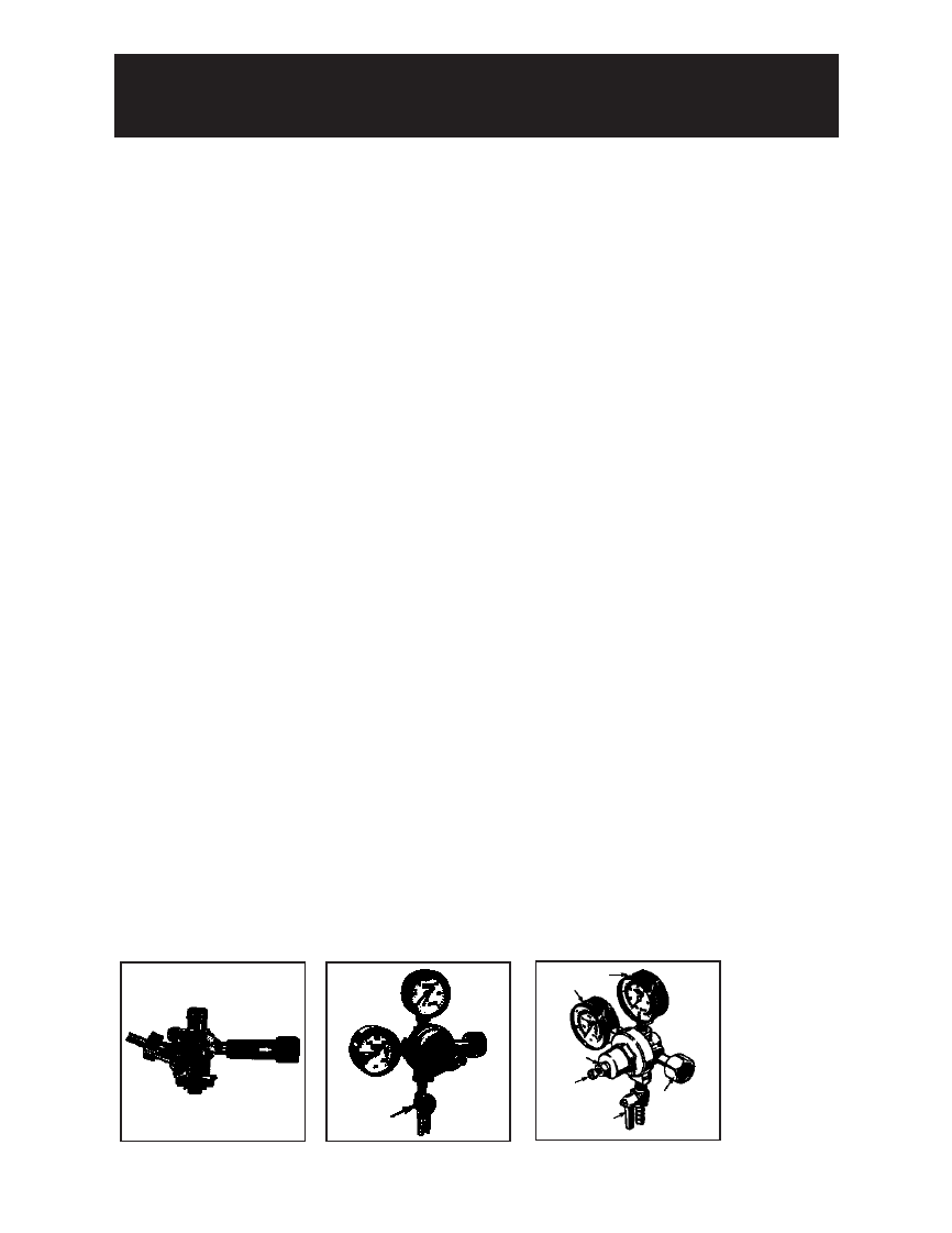
15. Adjusting the CO
2
Regulator: There are two
pressure gauges on the CO
2
regulator.
See Fig. 9: The upper gauge #1 monitors "LOW"
(internal keg) pressure and must be adjusted to
the correct operating pressure of 10~12psi/lbs.The
lower gauge #2 monitors "HIGH" (CO
2
cylinder)
pressure and is not adjustable. The high pressure
gauge also acts as a fuel gauge to let you know
when the C0
2
cylinder needs re-filling.
IMPORTANT: The internal operating pressure of the
beer keg should be adjusted and maintained between
10 ~ 12psi/lbs. To adjust the "low" pressure gauge;
• Using an adjustable wrench, release the adjustment
lock nut # 3. See Fig. 9
• Using a flat screwdriver, turn the regulator adjustment
screw (# 4 in Fig. 9): A clockwise rotation of the
regulator adjustment screw will increase low pressure,
a counter clockwise rotation of the adjustment
regulator adjustment screw will decrease low pressure
• When the required operating pressure is attained
retighten the adjustment lock nut # 3.
• You are now ready to serve cold beer
Fig. 7
Fig. 8
Fig. 9
2
1
4
5
6
3
Secondary
Shut-off
Valve
SETTING UP YOUR KEG COOLER
ASSEMBLY INSTRUCTIONS (CONT’D)
12
INSTRUCCIONES DE ARMADO (CONT.)
7. Instalación de la manguera de aire del cilindro
de CO2 al Regulador: Coloque un extremo de la
manguera de aire (roja) en la conexión del
regulador de CO
2
.
Fije la manguera con una de las dos abrazaderas
a presión (auto ajustables) proporcionadas. (Use
una pinza para ajustar la abrazadera y asegurarse
de que no haya pérdidas). Ver Fig. 5.
8. Instalación de la junta de la Torre de Cerveza:
Coloque la junta de goma (de la torre de cerveza)
directamente sobre el gabinete, alineando los cua
tro agujeros de la junta con cuatro agujeros del
gabinete.
9. Instalación de la Torre de Cerveza:
Desenrede la manguera de la cerveza de la
torre e insértela junto con la tuerca de
mariposa a través de la junta y en el gabinete.
Esto requerirá un poco de destreza colocando
(doblando) la tuerca de mariposa (junto con la
manguera de la cerveza) en posición vertical y
empujándola a través del orificio. Alinee los
cuatro agujeros en la base de la torre de
cerveza, junta y bayoneta. La canilla de la
cerveza debe quedar alineada con el frente del
gabinete. (En la posición de las 6:00 en punto).
Fije firmemente la torre de cerveza al gabinete
con un destornillador Phillips y los cuatro tornillos
para metal suministrados. Para
quitar (remover) el conjunto de torre de
cerveza del gabinete, sujete la torre y gírela
1/4 de vuelta en sentido contra horario (hasta
que se detenga) y tire hacia arriba.
10. Instalación de la Manija de la Canilla de la
Torre de Cerveza: Atornille la manija negra de la
canilla (en sentido horario) a la canilla de la torre
de cerveza. (Ajústela con la mano únicamente).
14. Instalación del acople del Barril: NOTA
IMPORTANTE: Asegúrese de que la manija negra
del acople del barril esté en posición vertical
(cerrada) antes de colocarla en el barril de
cerveza. Ver Fig. 8. Inserte el acople del barril en
el cuello de encastre del barril de cerveza y hágalo
girar 1/4 de vuelta en sentido horario para que se
trabe en su lugar.
15. Instalación de la manguera de
CO
2
al acople
del barril: Coloque el extremo libre de la
manguera de aire (roja) en la conexión del acople
del barril. Fije la manguera con la abrazadera
restante a presión (auto ajustables) proporcionada.
(Use una pinza para ajustar la abrazadera y
asegurarse de que no haya pérdidas).
16. Instalación de la manguera de cerveza al
acople del barril: Atornille la tuerca de la
manguera de cerveza al acople del barril y ajústela
firmemente con la mano. NOTA IMPORTANTE: La
arandela de goma negra suministrada debe
instalarse dentro de la tuerca de conexión de la
manguera de cerveza antes de conectarla al
acople del barril.
Fig. 5
PREPARACIÓN
Fig. 6
 Manymanuals.com
 Manymanuals.de
 Manymanuals.fr
 Manymanuals.it
 Manymanuals.pl
 Manymanuals.cz
 Manymanuals.es
 Manymanuals-pt.com
Comments to this Manuals